I prototyped each of the subsystems individually on bread board before combining them and installing.
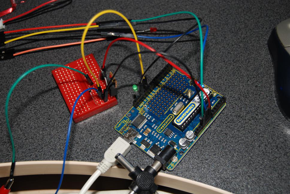
I'm using a TwentyTen from Freetronics here; this is compatible with the Arduino Duemilanove with the main differences being a USB mini connector and a prototyping area on the board. I like the idea of a prototyping area on the board but in practice I can't stand to use them so I have many bread boards instead which I can build and tear down non-destructively.
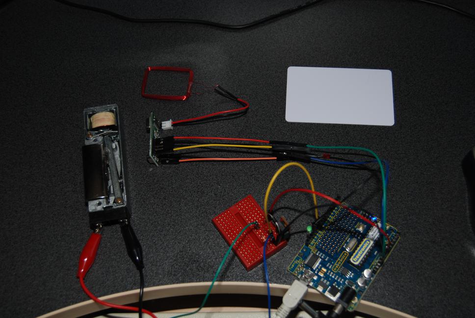
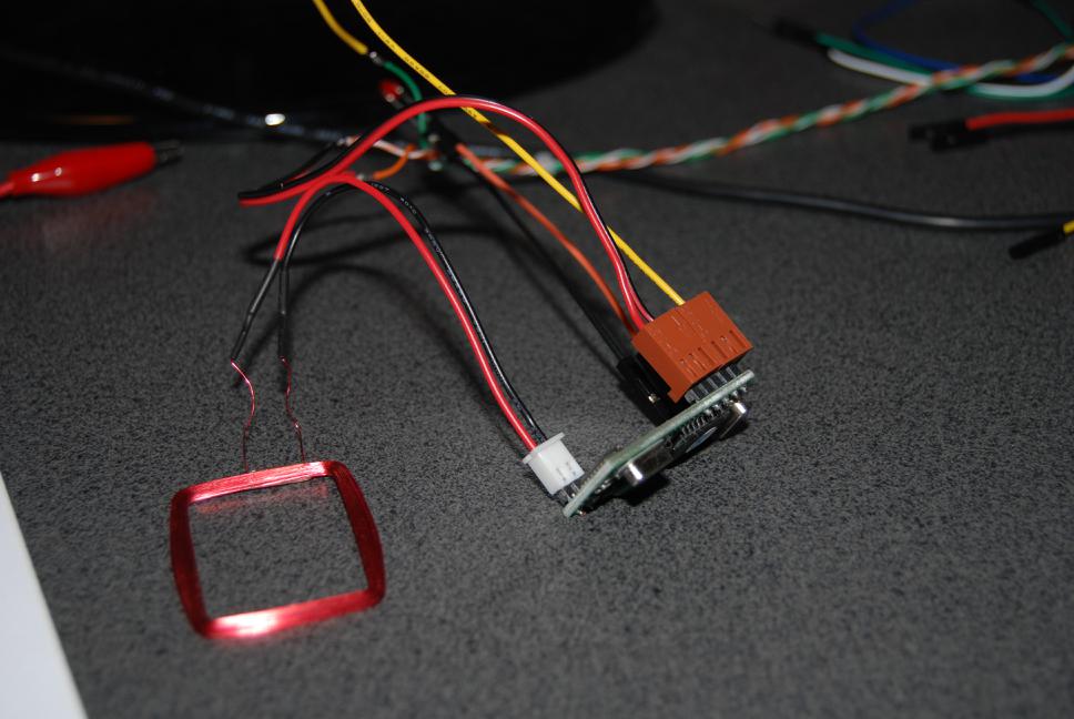
Attaching the RFID reader was trivial; it needed only 3 wires: GND, +5v and TX (transmit from the reader's perspective). This reader also includes an RX pin but I have no idea what commands it accepts.
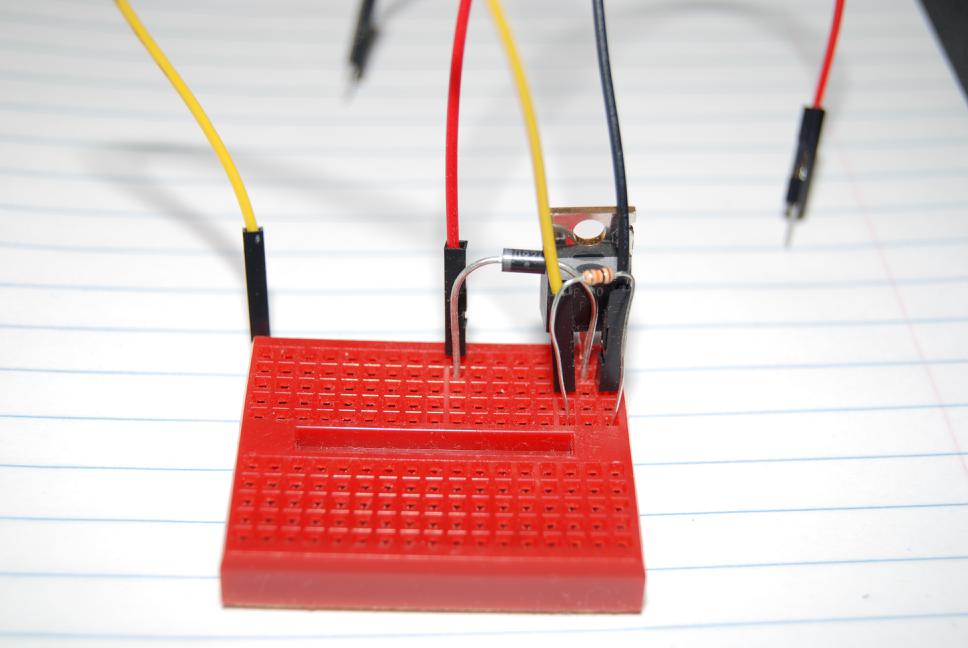
To power the electric strike I used a MOSFET (type IRF530), which is a type of high current transistor. I have seen other projects online (including Jon Oxer's RFID door lock) which use a relay to control high current devices but I wanted something solid-state. Also relays require some current to trip, probably more than the Arduino should be asked to provide, so a switching transistor is required regardless. Might as well combine them into a single component.
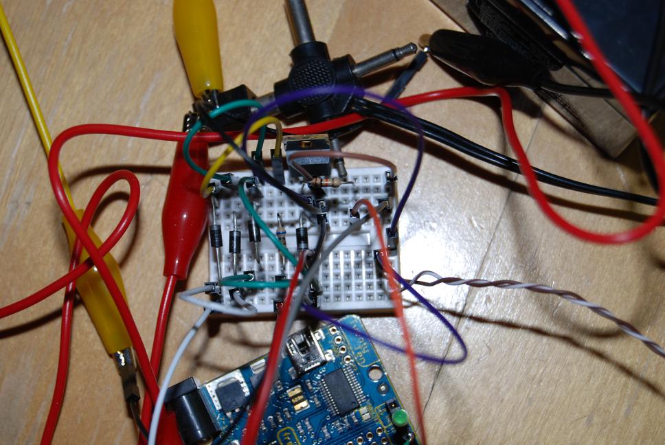
The battery backup circuit started out as a couple of diodes: the Arduino can draw current from either the battery or the mains (via plug pack). But that would eventually drain the battery. So the battery should also be trickle-charged. This led to a combined circuit; when mains voltage is applied the battery will be charged (at around 14v) with a current which is big enough to keep it topped up and small enough to not destroy the battery.